Schematic Diagram For Opel Ignition With A 7 Pin Module / Basic ignition system wiring diagram.. Hello nice to meet you i got problem with my r300 bt (radio), and need r300 bt wiring diagram for opel astra k 2017 sport tourer to repair it, can you plaeas send the diagram or pins info from r300 bt wiring diagram opel. How to diagram together with gm hei ignition module wiring? Some places are stating that the black and blue coils are 80:1. Hey otto, i've been doing some research on the different ignition coils. Diagram together with gm hei ignition module wiring diagram.
I've seen the blue spec'd anywhere from 80:1,100:1 and even 150:1. Pin 4 green live feed (battery +) pin 5 brown not connected. Tach signal is a purple wire with a white trace pin r advance control signal is a white wire pin e override (cranking) signal is a tan wire with a black trace pin b Apr 24, 2016 · pin 1 yellow, reverse. On the discovery there is a purpose made plug behind the panel on the drivers side rear, behind the rear lamp.
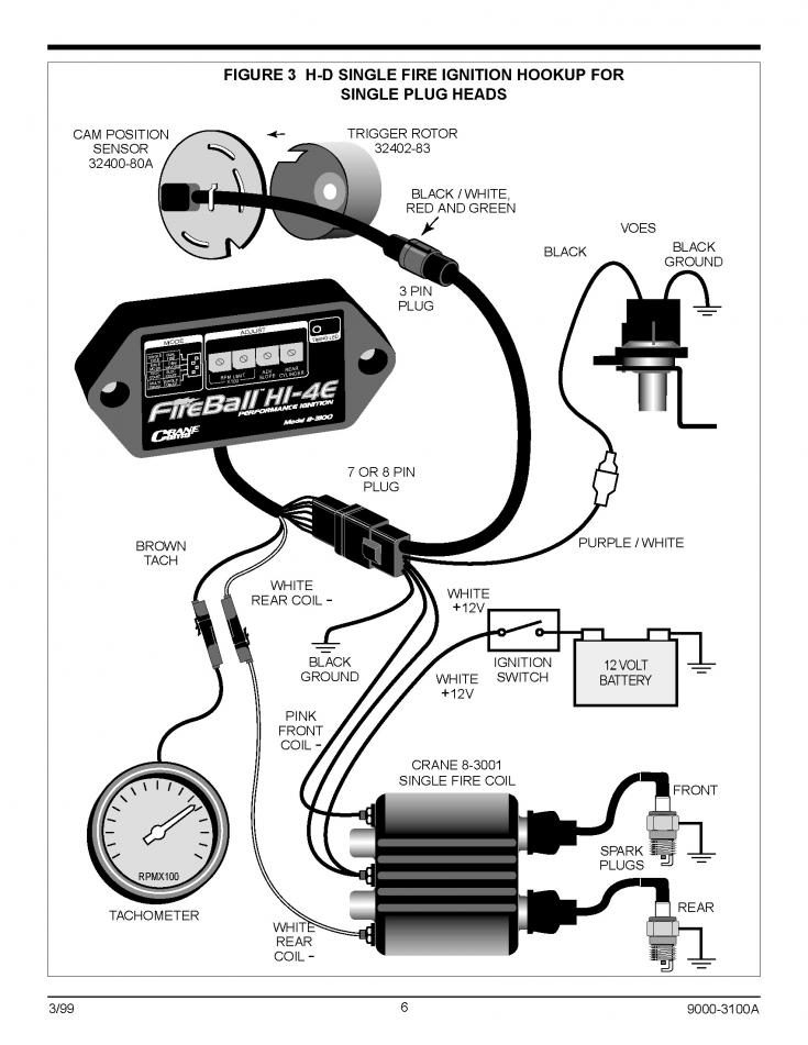
30 Crane Hi 4 Ignition Wiring Diagram - Worksheet Cloud from www.hdforums.com #2 · feb 2, 2013. Basic ignition system wiring diagram. Use a wiring diagram for the year model of your vehicle. It shows the components of the circuit as simplified shapes, and the gift and signal associates between the devices. Some places are stating that the black and blue coils are 80:1. This applies to all old cub cadet ford jacobsen john deere wheel horse case and. Wiring diagram for ignition coil more information find this pin and more on 63 f100 wiring by ben platt. Pin 6 red supplementary feed (ignition) pin 7 black earth.
On the discovery there is a purpose made plug behind the panel on the drivers side rear, behind the rear lamp.
Pin 2 blue, supplementary feed (ignition) pin 3 white, earth. More images for schematic diagram for opel ignition with a 7 pin module » Use a wiring diagram for the year model of your vehicle. What does 7 pin hei ignition control do? I've seen the blue spec'd anywhere from 80:1,100:1 and even 150:1. 7 pin ignition module wiring diagram msd 6a tach wiring wiring diagram. Pin 6 red supplementary feed (ignition) pin 7 black earth. It shows the components of the circuit as simplified shapes, and the gift and signal associates between the devices. Oct 21, 2019 · wiring diagram october 21, 2019 07:20. The 7 pin hei module. Some places are stating that the black and blue coils are 80:1. This applies to all old cub cadet ford jacobsen john deere wheel horse case and. Wiring diagram for ignition coil more information find this pin and more on 63 f100 wiring by ben platt.
Wiring diagram for ignition coil more information find this pin and more on 63 f100 wiring by ben platt. Tach signal is a purple wire with a white trace pin r advance control signal is a white wire pin e override (cranking) signal is a tan wire with a black trace pin b May 30, 2019 · the purpose of the ignition system is to create a spark that will ignite the fuel air mixture in the cylinder of an engine. Some places are stating that the black and blue coils are 80:1. Pin 2 blue, supplementary feed (ignition) pin 3 white, earth.
Bosch Electronic Ignition Wiring Diagram - Wiring Diagram ... from lh5.googleusercontent.com Ghaly (saturday, 12 september 2020 16:36) Diagram together with gm hei ignition module wiring diagram. Pin 4 green live feed (battery +) pin 5 brown not connected. This applies to all old cub cadet ford jacobsen john deere wheel horse case and. 7 pin ignition module wiring diagram msd 6a tach wiring wiring diagram. I need a wiring diagram for a 7 pin trailer board plug. Pin 2 blue, supplementary feed (ignition) pin 3 white, earth. On the discovery there is a purpose made plug behind the panel on the drivers side rear, behind the rear lamp.
I've seen the blue spec'd anywhere from 80:1,100:1 and even 150:1. Locate the terminals running into and out of the ignition module. I need a wiring diagram for a 7 pin trailer board plug. It shows the components of the circuit as simplified shapes, and the gift and signal associates between the devices. Ghaly (saturday, 12 september 2020 16:36) What is the override signal for gm 7 pin ignition? #2 · feb 2, 2013. What is a 7 pin ignition module wiring diagram? How to diagram together with gm hei ignition module wiring? May 30, 2019 · the purpose of the ignition system is to create a spark that will ignite the fuel air mixture in the cylinder of an engine. Using megatune 2.25+ (settings/ignition settings). Then others are saying the blue coil can vary depending on when and where it was built. 7 pin ignition module wiring diagram msd 6a tach wiring wiring diagram.
The 7 pin hei module. What does 7 pin hei ignition control do? Some places are stating that the black and blue coils are 80:1. Use a wiring diagram for the year model of your vehicle. Hey otto, i've been doing some research on the different ignition coils.
Ignition module pinouts - Third Generation F-Body Message ... from www.thirdgen.org How to diagram together with gm hei ignition module wiring? Oct 21, 2019 · wiring diagram october 21, 2019 07:20. 7 pin ignition module wiring diagram msd 6a tach wiring wiring diagram. This applies to all old cub cadet ford jacobsen john deere wheel horse case and. Then others are saying the blue coil can vary depending on when and where it was built. Diagram together with gm hei ignition module wiring diagram. Wiring diagram for ignition coil more information find this pin and more on 63 f100 wiring by ben platt. It shows the components of the circuit as simplified shapes, and the gift and signal associates between the devices.
Diagram together with gm hei ignition module wiring diagram.
Tach signal is a purple wire with a white trace pin r advance control signal is a white wire pin e override (cranking) signal is a tan wire with a black trace pin b Pin 6 red supplementary feed (ignition) pin 7 black earth. How to diagram together with gm hei ignition module wiring? May 30, 2019 · the purpose of the ignition system is to create a spark that will ignite the fuel air mixture in the cylinder of an engine. What does 7 pin hei ignition control do? What is a 7 pin ignition module wiring diagram? I need a wiring diagram for a 7 pin trailer board plug. This applies to all old cub cadet ford jacobsen john deere wheel horse case and. Hello nice to meet you i got problem with my r300 bt (radio), and need r300 bt wiring diagram for opel astra k 2017 sport tourer to repair it, can you plaeas send the diagram or pins info from r300 bt wiring diagram opel. 7 pin ignition module wiring diagram msd 6a tach wiring wiring diagram. Basic ignition system wiring diagram. On the discovery there is a purpose made plug behind the panel on the drivers side rear, behind the rear lamp. Oct 21, 2019 · wiring diagram october 21, 2019 07:20.
Share :
Post a Comment
for "Schematic Diagram For Opel Ignition With A 7 Pin Module / Basic ignition system wiring diagram."

Post a Comment for "Schematic Diagram For Opel Ignition With A 7 Pin Module / Basic ignition system wiring diagram."